Hydraulic system schematics Troubleshooting tips for hydraulic systems Basics of hydraulic systems
Gravely 51000 24-G Parts Diagram for HYDRAULIC SYSTEM
Figure 4-4. hydraulic system , schematic diagram 2320 tm foldout Diagram hydraulic schematic make
Circuits enggcyclopedia ebooking
Hydraulic diagram figure tmTm 1520 hydraulic schematic continued interconnecting apu major system ch end Hydraulic diagramAircraft systems: basic hydraulic systems.
Figure fo-3. hydraulic system schematic (foldout 5 of 8)Ago schematic hydraulic tm Schematic of hydraulic system.Hydraulic system diagram parts gravely wheel diagrams great tractors.

Hydraulic system schematic.
Hydraulic schematic system diagram tmHydraulic symbols system drawing circuit engineering diagram pump mechanical simple beginners electrical cylinder fluid pnuematic valves valve basic hydraulics symbol Hydraulic system schematicsFigure 4-35. hydraulic system, schematic diagram..
Hydraulic systemFigure 6. schematic hydraulic diagram Hydraulic schematic system diagram wiringMajor interconnecting apu hydraulic system schematic (continued).

Schematic diagram of the proposed hydraulic system having the advance
System hydraulic diagram schematic tmHow to make a wiring diagram Figure 3-59. hydraulic system schematic diagramHydraulic system schematic diagram.
Hydraulic diagram system tm schematic figureBasic diagrams and systems Hydraulic system for beginnersFigure 4-8. hydraulic system diagram..

Hydraulic schematics
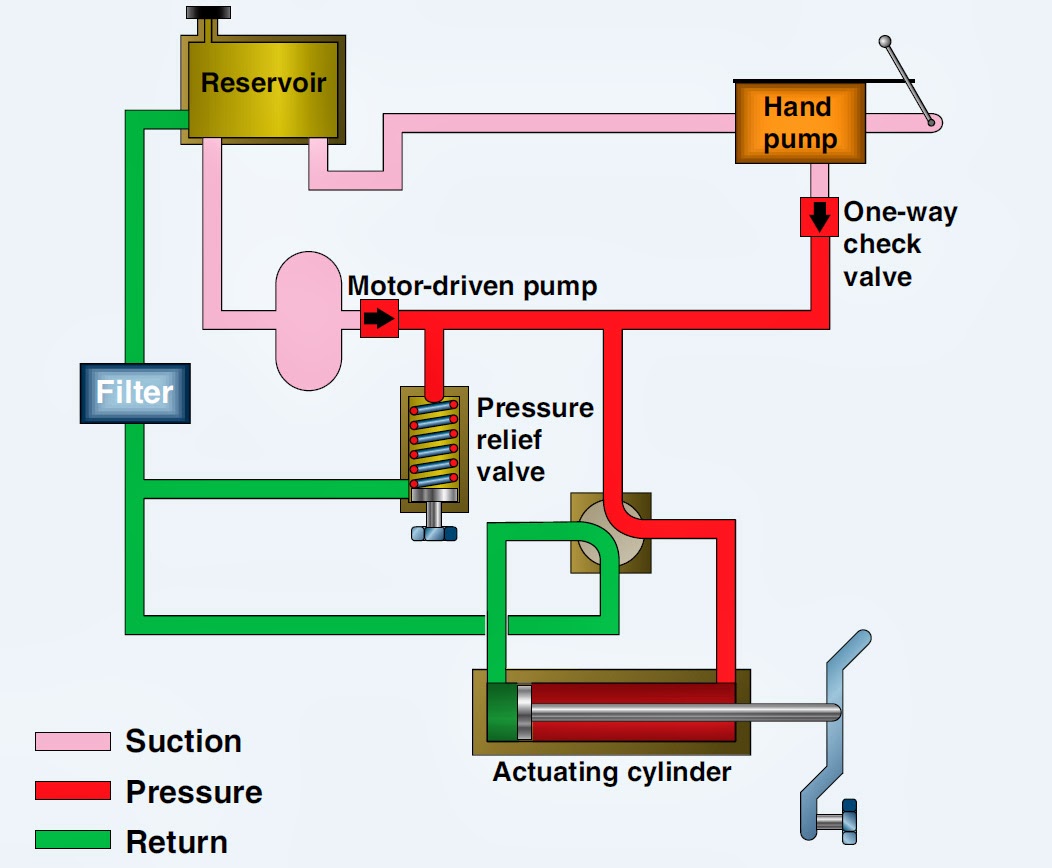
Basic components and its functions of a hydraulic systemHydraulic basic system aircraft systems examples power gear diagram law schematic hydraulics control landing pascal components down figure mechanical Tm hydraulic schematic sheet figure systemDiagrams hydraulic pictorial hydraulics cutaway.
Hydraulic tm diagram system fittings linesPatent us20080083222 Hydraulic schematic tmGravely 51000 24-g parts diagram for hydraulic system.

Figure 4. hydraulic system schematic (sheet 5 of 5).
Schematic hydraulic system – the wiring diagram – readingrat.netHydraulic systems troubleshooting diagram system basic typical components machine supply tips data Hydraulic proposedHydraulic functions syste.
Figure fo-3. hydraulic system schematic (foldout 6 of 8)Patents hydraulic claims Figure 1-4. hydraulic diagram.


Figure 4-4. Hydraulic System , Schematic Diagram

Figure 4. Hydraulic System Schematic (Sheet 5 of 5).

HYDRAULIC SYSTEM FOR BEGINNERS - Mechanical Engineering Professionals

Schematic diagram of the proposed Hydraulic system having the advance

Basic Diagrams and Systems | Engineering Library

Schematic Hydraulic System – The Wiring Diagram – readingrat.net

Aircraft systems: Basic Hydraulic Systems